

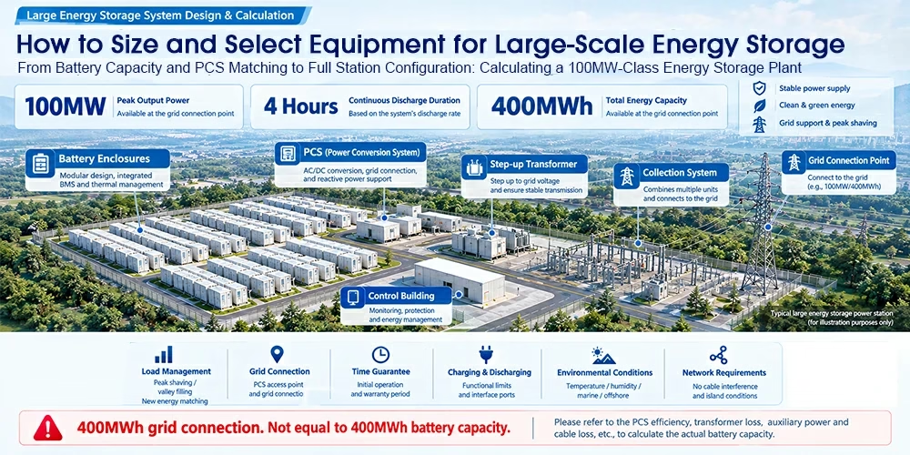
Selection does not start with the question “how many batteries should we install” — it starts with “what must we deliver.” This article walks through a worked example of a 100MW-class energy storage plant. Starting from the delivery boundary, it explains the complete logic step by step: deriving battery capacity, selecting PCS units, configuring the full station, and comparing design strategies.
1. Define the Requirements First, Then Calculate the Scale
The first step in energy storage selection is to clarify the delivery boundary before deriving the installed configuration.
For this project, the delivery requirements are:
- Net output power of 100 MW: the available output power at the grid connection point
- Continuous discharge duration of 4 hours: the time the plant can discharge at rated power
- Net delivered energy of 400 MWh: the total usable energy at the grid connection point
The relationship among the three is straightforward:
Required energy = Power × Duration, i.e., 100 MW × 4 h = 400 MWh
A typical large-scale energy storage plant uses battery container arrays as its core energy storage units, with engineers designing them by rack or system. The PCS converter-transformer integrated cabins convert power between DC and AC while providing grid support. Step-up transformers raise the voltage to the grid connection level. Collector circuits aggregate multiple feeders and connect them to the step-up substation. The control building monitors the system, manages protection, and oversees energy management. Finally, the grid connection point enables metering and delivers 100 MW / 400 MWh on a net basis.
Clarify the delivery boundary before calculating the scale
Before starting the calculation, you must confirm six dimensions with the owner and the grid operator:
| Dimension | What to clarify | Notes |
| Application task | Peak shaving / frequency regulation / renewable integration | Different applications demand different power, duration, and response characteristics |
| Metering point | Battery side / PCS outlet / grid connection point | Different metering points imply different energy and efficiency figures |
| Guarantee point | Beginning of life / end of life | Performance degradation across the lifecycle must be considered |
| Charging conditions | Power limits and charging windows | Constrained by the grid, the plant site, and renewable output |
| Site conditions | Temperature / altitude / land area | These affect battery performance, thermal design, and equipment selection |
| Grid code requirements | Reactive power / fault ride-through / grid-forming | The project must satisfy grid codes and interconnection conditions |
2. How Much Battery Capacity Do You Need? Deriving Nominal Capacity from Net Delivered Energy
Assumptions for this worked example (illustrative parameters):
- Net delivered energy at the grid connection point: 400 MWh
- Auxiliary consumption (referred to the grid connection point): 2 MWh
- Usable SOC range: 90%
- One-way discharge efficiency: 96%
- Capacity retention at beginning of life: 100%
- Capacity retention at end of life: 80%
Core formula:
Nominal capacity = (Net delivered energy + Equivalent auxiliary consumption) ÷ (Usable SOC ratio × Capacity retention × One-way discharge efficiency)
Two configuration approaches
Approach 1: Meet the requirement at beginning of life (configure for the initial state and satisfy the net delivery requirement at commissioning)
402 ÷ (90% × 100% × 96%) ≈ 465.3 MWh
Assuming 5 MWh per container, the plant requires 94 containers ≈ 470 MWh
Approach 2: Meet the requirement at end of life without mid-life augmentation (configure for the end-of-life state across the project lifecycle)
402 ÷ (90% × 80% × 96%) ≈ 581.6 MWh
Assuming 5 MWh per container, the plant requires 117 containers = 585 MWh
Three important verification reminders
- The container count is a lower bound from the energy calculation; you must round it according to system grouping. In practice, you should round the count to comply with PCS capacity, system grouping, and electrical topology requirements.
- One-way discharge efficiency ≠ round-trip efficiency. This calculation uses one-way discharge efficiency; round-trip efficiency ≈ charging efficiency × discharging efficiency, which is typically lower.
- If a vendor quotes AC-side usable energy, check what has already been deducted. Confirm whether the SOC range, efficiency, auxiliary consumption, and capacity degradation have already been subtracted, so you neither deduct them twice nor miss them.
3. PCS Selection Is Not Just About MW — Check Active Power, Reactive Power, DC Limits, and Site Conditions Together
Assumptions for this example: net grid-side output of 100 MW; auxiliary loads equivalent to 0.5 MW at the grid connection point; AC-path efficiency of 99%.
PCS power ≥ (100 + 0.5) ÷ 99% ≈ 101.52 MW
Assuming each unit provides 2.5 MW of continuous active power, the required quantity is ≥ ceil(101.52 ÷ 2.5) = 41 units
⚠️ Note: 41 units is only the lower bound from the active power calculation. Actual selection must account for reactive power, DC limits, site conditions, and project interconnection requirements.
Six aspects to verify during selection
| Check item | Key question |
| Continuous power | How much output remains at high temperature and high altitude? |
| DC voltage | Does the unit stay within range across the full SOC window? |
| Charging capability | Can the battery fully charge within the charging window? |
| Reactive capability | How much reactive power can the unit provide while delivering active power? |
| DC current | Can the unit maintain power at low voltage? |
| Grid performance | Do the control and grid-support capabilities meet the requirements? |
Key formulas:
Apparent power S ≥ √(P² + Q²); DC current I ≈ DC power ÷ DC voltage
Note: MW denotes active power and MVA denotes apparent power; the 99% figure represents the AC-segment efficiency, which is already included in the complete one-way path and must not be deducted twice.
4. From Equipment Counts to Full Station Configuration — Electrical Matching, System Grouping, and Site Layout Are All Essential
Once you have the battery container count and the PCS unit count, you must organize them into a plant that can actually connect to the grid. The electrical path runs:
Battery racks → PCS → Unit step-up transformer → Medium-voltage collection → Main transformer (if required) → Grid connection point
On the control side, the BMS monitors battery status, alarms, and protection; the PCS handles power conversion, operation control, and power regulation; the EMS coordinates operation, manages energy, and optimizes dispatch strategies; and the plant controller manages grid connection control, interconnection strategy, and dispatch interfaces.
Four building blocks of full station configuration
01 Storage units — battery-PCS matching, interfaces, and unit-level power and energy
- Capacity matching between battery containers and PCS units
- DC/AC interface design
- Power and energy configuration per unit
- Unit grouping and scalability
02 Step-up and collection — transformer capacity, feeder grouping, and active/reactive power flow
- Transformer capacity planning
- Medium-voltage feeder grouping schemes
- Active and reactive power flow calculations
- Collection schemes and wiring configurations
03 Electrical protection — ampacity, voltage drop, short-circuit withstand, and protection coordination
- Cable ampacity verification
- Voltage drop calculation
- Short-circuit withstand verification
- Protection settings and coordination
04 Site and utilities — thermal management, fire protection, station power, and maintenance access
- Thermal management and ventilation design
- Fire protection system configuration
- Station auxiliary power system
- Layout of maintenance and transport access
⚠️ Important reminder: 94 or 117 containers and 41 PCS units are lower bounds calculated separately — they are not a procurement list. Different technical solutions, vendor equipment, and project conditions lead to different configurations, so you must validate them against the specific project.
The complete set of deliverables
From calculation to drawings, you should produce five core technical documents: an equipment configuration table (equipment list, quantities, and key parameters), a single-line diagram (electrical connections and protection configuration), a general layout drawing (functional zoning and equipment placement), a station power load table (auxiliary loads and their configuration), and a performance guarantee table (key performance indicators and guarantee requirements).
5. When Is a Design Right? Verify Performance, Lifetime, and Full-Cycle Cost Together
Comparing three selection strategies
Different strategies suit different project conditions and goals, so you should weigh grid requirements, site conditions, and long-term planning together:
| Strategy | Approach | Key concerns | Best suited for |
| Over-provision at the start | Install extra capacity up front to absorb degradation | Initial investment, land use, early-life utilization | Projects with strict delivery obligations that want to avoid mid-life augmentation |
| Phased augmentation | Add equipment gradually as capacity degrades | Interface reservation, compatibility, construction downtime | Projects built in phases with room for expansion that want to optimize initial investment |
| Accept capacity fade | Reduce delivered capacity year by year per contract | Whether later-period energy still meets demand | Projects whose energy demand declines over time and that can accept fade |
Six questions every selection must answer
- Is the energy sufficient? — Can the plant deliver 400 MWh net at the assessment point?
- Is the power sufficient? — Can it sustain 100 MW output under adverse conditions?
- Can it charge fully? — Are the charging power and window adequate?
- Can it connect? — Do voltage, reactive power, protection, and control all match the grid?
- Does it fit the site? — Is there enough space for maintenance, fire protection, and expansion?
- Is it economical over the full cycle? — Have losses, O&M, degradation, and augmentation been factored in?
Worked example — summary of initial results
| Item | Result |
| Net grid-side output target | 100 MW for 4 hours |
| Configuration at beginning of life | 470 MWh, 94 × 5 MWh containers |
| Configuration at end of life without augmentation | 585 MWh, 117 × 5 MWh containers |
| PCS active power lower bound | 41 units × 2.5 MW |
Conclusion
Guarantee the delivery capability under the agreed conditions, and compare the full-life cost — these are the two guiding principles of energy storage selection. This example has completed the initial power and energy calculations. As the next step, you must refine the design against reactive power, derating, system grouping, and interconnection conditions before it becomes an executable engineering plan.
This article is a worked teaching example, and all parameters are assumed. Actual equipment selection must follow vendor performance data, warranty terms, and project interconnection conditions.
