Introduction: Meeting Growing Enterprise Power Demands
To begin with, as businesses expand and electricity consumption increases, the ability to scale energy storage capacity quickly becomes critical. Therefore, LVFU’s commercial and industrial (C&I) energy storage systems are engineered with modular architecture and flexible expansion capabilities. Consequently, enterprises can add new battery cabinets to existing installations without disrupting ongoing operations.
In the following sections, This comprehensive guide explores how LVFU C&I energy storage systems achieve rapid capacity expansion to meet evolving enterprise power requirements. Ultimately, the goal is to help enterprises meet evolving power requirements efficiently and cost-effectively.
Understanding LVFU’s Modular Energy Storage Architecture
The LF-ESS261 System: Built for Scalability
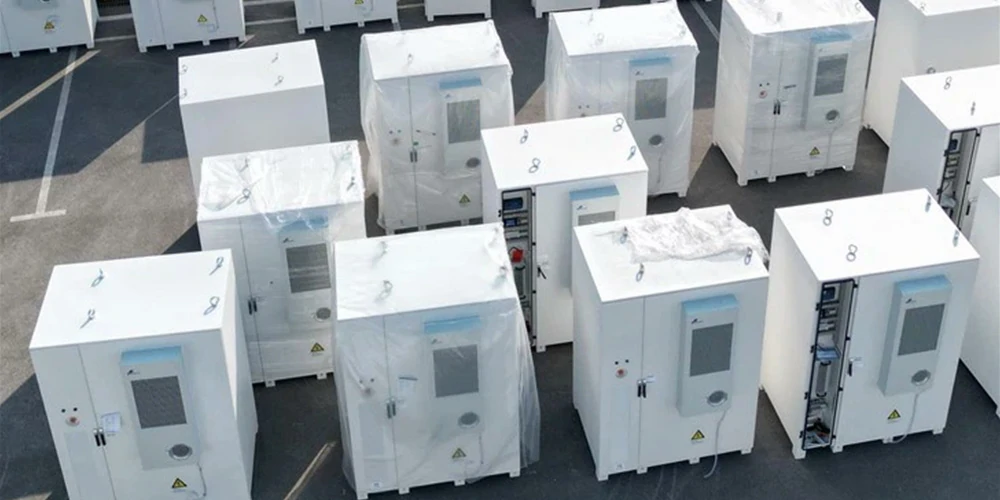
To illustrate, LVFU’s flagship LF-ESS261 industrial and commercial energy storage system exemplifies the company’s commitment to flexible expansion. More specifically, this integrated solution combines the following key components:
| Component | Function | Capacity |
| Battery Cabinet | Energy storage clusters, fire protection, liquid cooling | 261 kWh per unit |
| Electrical Cabinet | PCS, EMS, MPPT, STS | Manages up to 4 battery cabinets |
| Thermal Management | Liquid cooling system | Maintains optimal battery temperature |
| Safety Systems | Multi-level fire protection | Detection, suppression, explosion venting |
What sets this system apart is its key scalability feature.
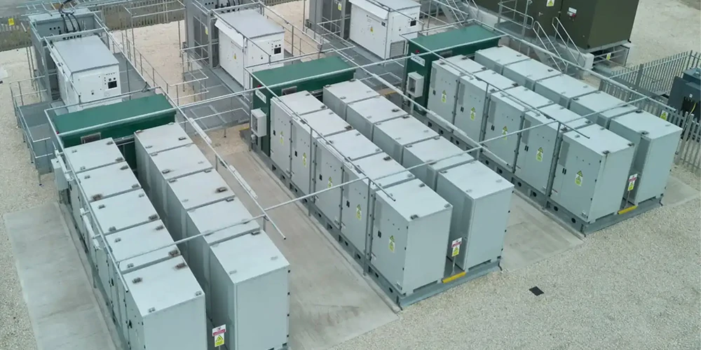
In fact, the LF-ESS261 supports parallel operation of up to four battery cabinets with a single 400V electrical cabinet. As a result, system duration can be extended from 2 hours to 8 hours without replacing any core infrastructure.
Technical Approaches to Capacity Expansion
1. AC-Side Expansion (Parallel Connection)
To begin, the most common method for expanding LVFU energy storage capacity involves AC-side parallel connections:
Here is how it works in practice:
- First, New battery cabinets connect to the existing electrical cabinet’s AC output
- Then, Each additional cabinet operates in parallel with existing units
- At the same time, The integrated PCS (Power Conversion System) manages power flow coordination
- Meanwhile, EMS (Energy Management System) optimizes charging/discharging across all units
As a result, this method offers several advantages:
✅ Minimal downtime during installation
✅ No modification to existing battery cabinets required
✅ Independent operation of each cabinet
✅ Easy maintenance and future upgrades
2. DC-Side Expansion (Battery Cluster Addition)
In contrast, for applications requiring higher voltage or extended duration, DC-side expansion offers another pathway:
Specifically, The implementation process is as follows:
1. First, additional battery clusters connect to the DC bus
2. Next, High-voltage boxes manage voltage regulation
3. Subsequently, BMS (Battery Management System) integrates new clusters into existing monitoring
4. Finally, System automatically recalibrates capacity and performance parameters
Thus, DC-side expansion provides a viable solution for more demanding power configurations.
Interface Pre-Design: The Foundation of Rapid Expansion
Why Interface Reservation Matters
It is important to note that successful rapid expansion begins with proactive design during initial deployment.
For this very reason, LVFU systems incorporate the following pre-installed connection points:
Pre-Installed Connection Points:
- Spare feeder breakers in electrical cabinets for future cabinet connections
- Communication ports (CAN/RS485/Modbus) pre-configured for additional units
- Pre-wired control cables with quick-connect terminals
- Reserved space for thermal management system expansion
Moreover, LVFU adopts a fully standardized module design, which includes:
- Uniform battery pack dimensions across product generations
- Compatible BMS communication protocols
- Consistent voltage and current ratings
- Interchangeable components for simplified maintenance
Consequently, interface reservation significantly reduces expansion time and complexity.
Step-by-Step: Adding New Energy Storage Cabinets
Phase 1: Pre-Installation Assessment
1. First, perform a load analysis to evaluate current and projected power consumption patterns.
2.Next, conduct capacity planning to determine required additional capacity (kWh) and power (kW).
3.Then, review existing infrastructure to verify that the electrical cabinet can support expansion.
4.Finally, prepare the site by ensuring adequate physical space and ventilation.
Phase 2: Physical Installation
1.To start, position the new cabinet adjacent to the existing system.
2.After that, make the electrical connections:
- Connect AC power cables to parallel bus
- Link communication cables to EMS
- Integrate thermal management systems
3.As a final step in this phase, integrate safety systems by connecting fire suppression and monitoring systems.
Phase 3: System Configuration
1.First, set up BMS parameters, including voltage, current, and temperature thresholds.
2.Next, integrate the EMS by updating energy management algorithms for the additional capacity.
3.Then, synchronize parallel operation to ensure seamless functioning with existing cabinets.
4.Afterwards, conduct performance testing to verify charge/discharge cycles and efficiency metrics.
Phase 4: Commissioning
1.System-Wide Testing: Run full capacity tests under various load conditions
2.Safety Verification: Confirm all protection systems function correctly
3.Performance Optimization: Fine-tune EMS settings for maximum efficiency