I. Core Definition and Distinction
The fundamental difference between GFM and Grid-Following (GFL) inverters lies in their control objective and physical behavior.
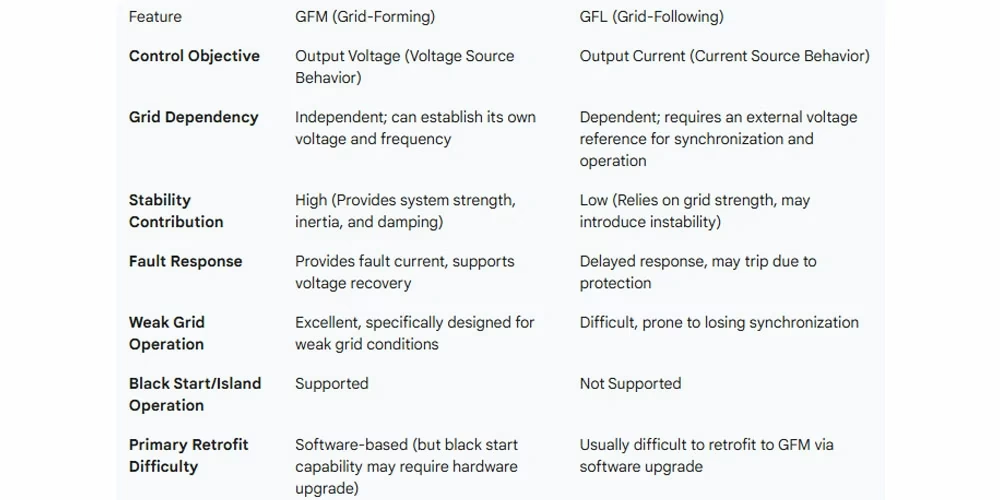
| Feature | GFM (Grid-Forming) | GFL (Grid-Following) |
| Control Objective | Output Voltage (Acts as a Voltage Source) | Output Current (Acts as a Current Source) |
| Behavior | Leader (Autonomously establishes and maintains grid voltage and frequency) | Follower (Must rely on an external stable voltage source for synchronization) |
| Key Physical Trait | Maintains a near-constant internal voltage phasor during sub-transient/transient time frames (milliseconds to $100ms). This is the basis for all stability contributions. | Must sync to the existing voltage phasor. |
Official Definition (Consolidated)
GFM is a function that allows an inverter to act as a voltage source by maintaining its own internal voltage phasor. It regulates active and reactive power based on grid demand, regardless of system strength, within its current and energy limits.
II. Core Capabilities and Value Proposition
GFM inverters provide Essential Reliability Services critical for high renewable penetration systems:
System Strength & Stability:
Provides Inertia & Damping to suppress oscillations and increase the system’s Short Circuit Ratio (SCR).
Excellent Weak Grid Operation (Tested to operate stably at SCR as low as 1.25).
Voltage & Frequency Support:
Provides near-instantaneous voltage and frequency regulation.
Fault Ride-Through (FRT):
Stays connected during faults and rapidly injects reactive current (within 15ms to 20ms) to support voltage recovery.
Grid Resilience:
Black Start Capabilities:
Can initiate system power recovery from a complete blackout by establishing the initial voltage and frequency.
Island Operation:
Can continue to power and stabilize a local isolated grid section after separation from the main grid.
Increased Hosting Capacity:
The stability services provided by GFM allow the power system to safely integrate a higher proportion of renewable energy.
III. Key Technical Requirements
The advanced capabilities of GFM rely on specific hardware and control features:
Overload Capability (Hardware Requirement):
Necessary to handle inrush currents (e.g., from transformers and motor start-ups) and provide sufficient fault current.
Fault Current Provision:
Must inject significant fault current (positive and negative sequence) to ensure proper operation of traditional protection equipment.
Self-synchronization:
Ability to detect grid conditions and automatically synchronize without relying on external signals.
Impedance Characteristics:
Ideally, GFM should exhibit positive resistance behavior to actively dampen system oscillations.
Adjustable Parameters:
Control parameters like frequency and voltage droop coefficients, dead band, and response times must be tunable by system operators.
IV. Applications, Deployment, and Trends
Primary Application Carrier:
Battery Energy Storage Systems (BESS) are the most mature and ideal platform, as they offer fast response, energy buffer, and often require only a software upgrade.
Optimal Deployment Location:
In the weakest parts of the grid (e.g., remote transmission ends, low-SCR nodes) to maximize stability enhancement.
Penetration Target:
Recommendations suggest that 25~30% of system resources should ideally be GFM-capable as a good starting point to maintain stability in high-renewable systems.
Industry Trends:
Accelerating Standards: Grid operators globally (AEMO, NGESO, Fingrid, HECO) are rapidly developing mandatory GFM standards.
Increased Commercial Deployment: Major projects (especially BESS) are actively implementing GFM control.
Market Mechanism: Emergence of market services that financially compensate GFM resources for providing essential stability services.
V. Challenges
Control Interaction:
Potential for control-loop interactions between multiple GFM devices or other equipment, requiring careful tuning and coordination.
Retrofit Difficulty:
Converting existing GFL inverters to GFM is often complex and sometimes impossible.
Standardization and Validation:
Global standards for modeling and performance validation are still evolving, and precisely verifying the “constant internal voltage phasor” behavior is technically challenging.