

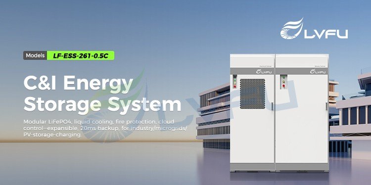
LF-ESS-261 125kW / 261kWh Commercial and Industrial Energy Storage System
The LF-ESS-261 is a commercial and industrial battery energy storage system with 261 kWh of nominal battery capacity and a 125 kW power conversion system (PCS). The system is designed for peak shaving, time-of-use energy management, solar self-consumption, backup power and microgrid applications.
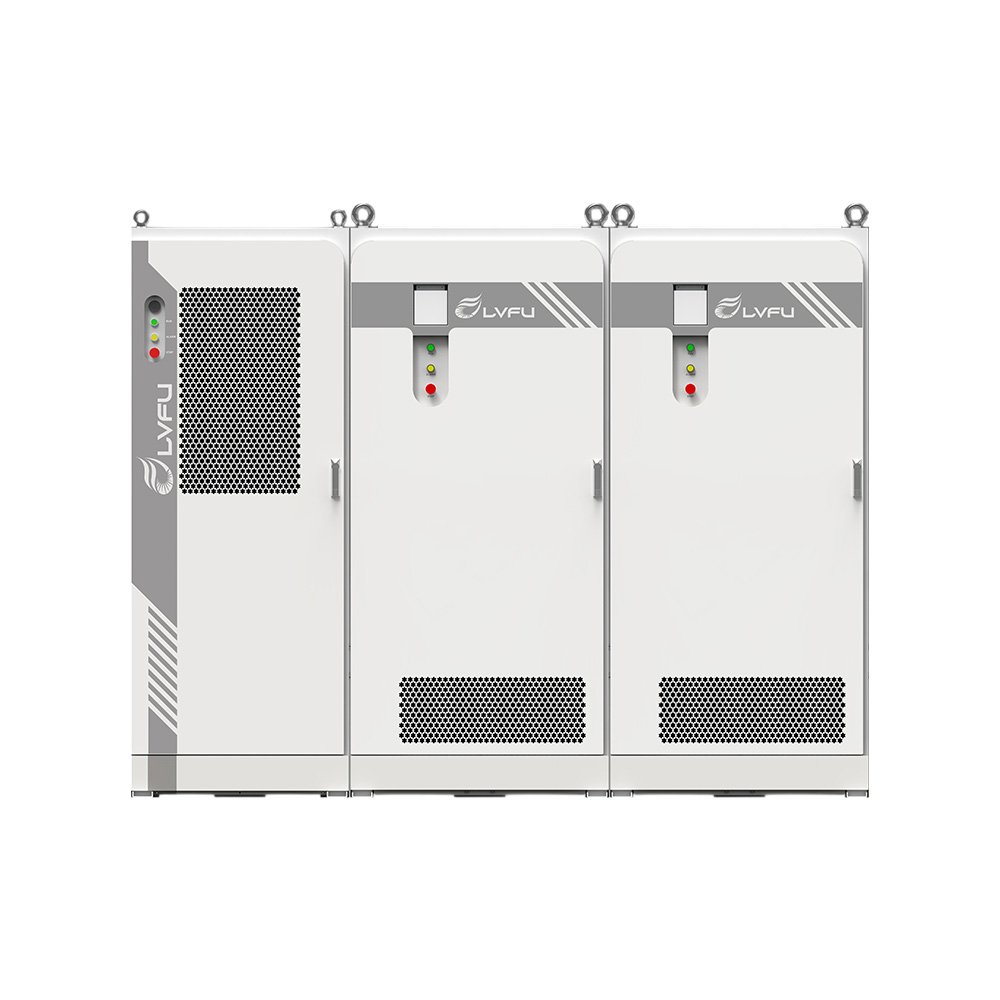
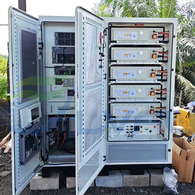
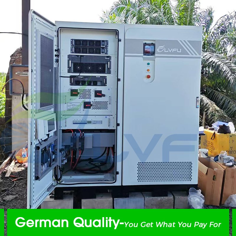
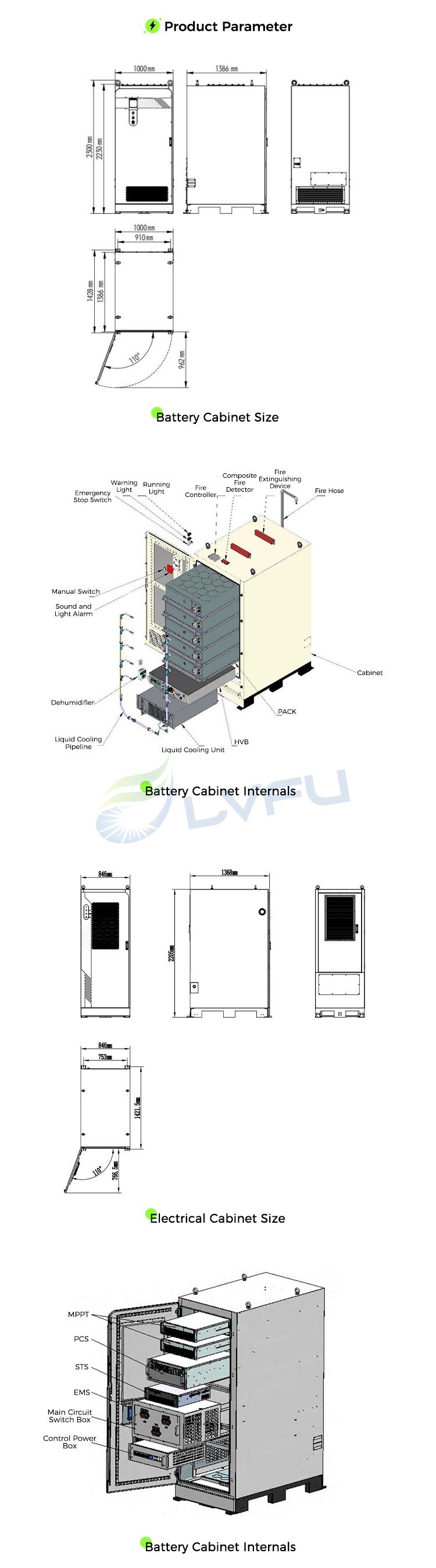
The standard configuration combines a 261 kWh liquid-cooled battery cabinet with a separate electrical cabinet. The battery cabinet contains five 52.2 kWh battery packs, a high-voltage box, liquid-cooling equipment and fire-protection components. The electrical cabinet integrates the PCS, EMS, two MPPT functions, STS and main-circuit protection.
Key Specifications
| Product model | LF-ESS-261 |
|---|---|
| Product category | Commercial and industrial battery energy storage system |
| Nominal battery energy | 261 kWh |
| PCS rated power | 125 kW |
| Cell chemistry and rating | LFP, 3.2 V / 314 Ah per cell |
| Battery pack configuration | 52 cells in series (52S), 52.2 kWh per pack |
| Battery system configuration | Five 52.2 kWh packs, 261 kWh total nominal energy |
| Battery voltage range | 702-936 V DC |
| Charge/discharge rate | 0.5C |
| Cooling method | Liquid cooling |
| Battery cabinet dimensions | 1000 x 1386 x 2230 mm (W x D x H) |
| Battery cabinet weight | 2376 +/- 50 kg |
| Ingress protection | Battery compartment IP55; liquid-cooling chamber IPX4 |
| Charging temperature | 1 to 56 degrees C |
| Discharging temperature | -28 to 56 degrees C |
| Allowable relative humidity | Below 95%, non-condensing |
| Maximum installation altitude | Up to 4000 m |
| Communication interfaces | RS485 and Ethernet |
| Communication protocols | IEC 61850, Modbus RTU and Modbus TCP |
Published ratings apply to the LF-ESS-F261kWh-0.5C battery cabinet. Final project performance depends on the selected electrical-cabinet configuration, usable state-of-charge window, site conditions and system design.
Battery Cabinet and Electrical Cabinet Architecture
The LF-ESS-261 uses separate battery and electrical cabinets. This architecture keeps battery storage and thermal management in the battery cabinet while placing power conversion, energy management, solar control and transfer switching in the electrical cabinet.
| Subsystem | Published configuration | Function |
|---|---|---|
| Battery cabinet | Five 52.2 kWh LFP packs, high-voltage box, liquid-cooling unit and fire-protection equipment | Stores 261 kWh of nominal DC energy and manages battery safety and temperature |
| PCS | 125 kW bidirectional power-conversion system | Converts battery DC power to AC power and AC power to DC for charging |
| EMS | Energy management system | Coordinates operating schedules, power flow and system monitoring |
| MPPT | Two MPPT functions in the published electrical-cabinet model definition | Controls DC-coupled photovoltaic input |
| STS | Static transfer switch | Transfers supported loads between grid-connected and backup operating states |
| Main-circuit protection | Main circuit switch box and control power box | Provides electrical isolation, distribution and protection |
System Diagrams and Installation References
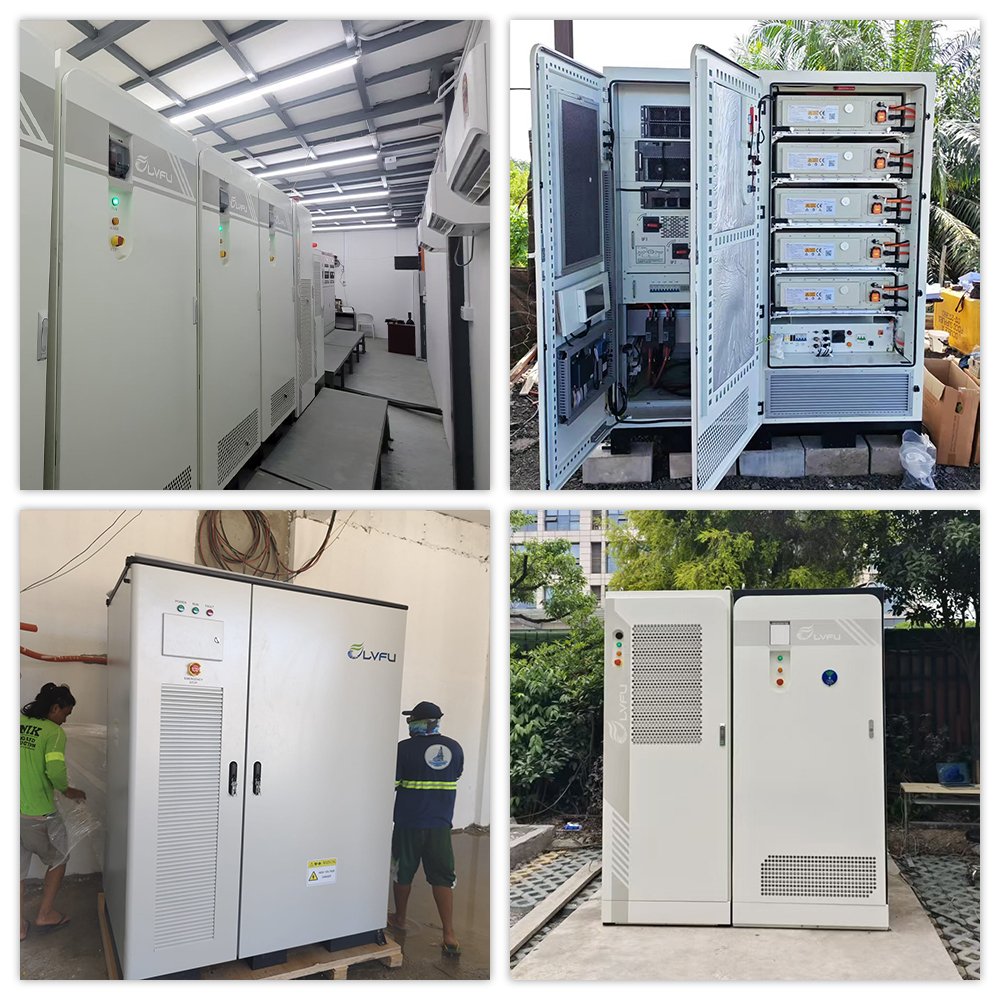
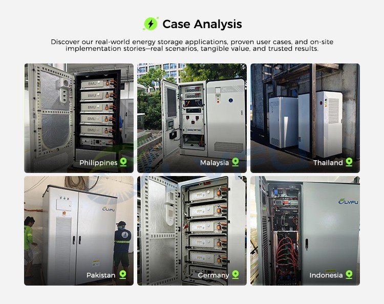
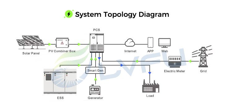
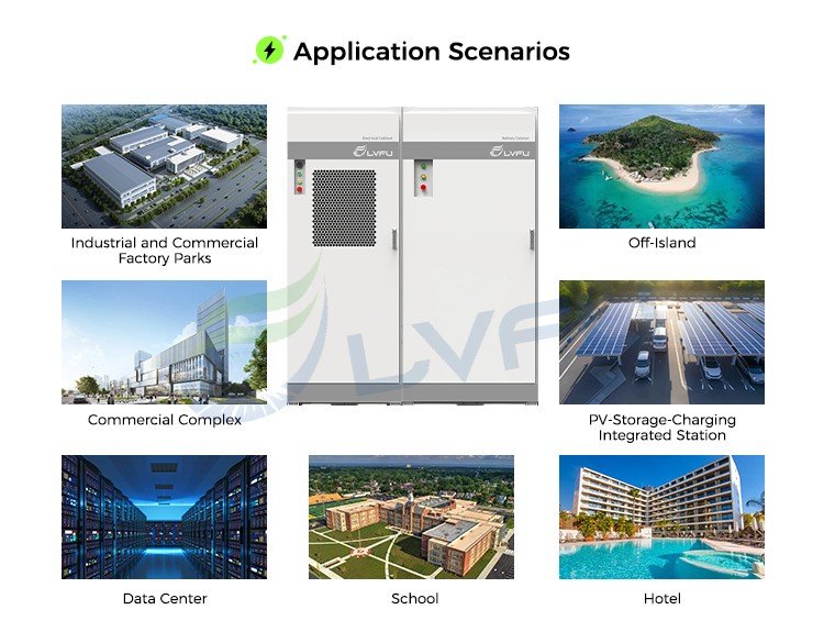
The diagrams below show the battery cabinet, electrical cabinet, system topology and representative application scenarios. Project wiring and component selection must follow the current LF-ESS-261 manual and the approved project design.
Why the LF-ESS-261 Uses a 125 kW PCS
A 261 kWh battery paired with a 125 kW PCS has a nominal energy-to-power ratio of approximately 2.09 hours. This is calculated as 261 kWh divided by 125 kW. The published 0.5C battery rating corresponds to approximately 130.5 kW at nominal capacity, so the 125 kW PCS rating is within the battery cabinet's published 0.5C power range.
This calculation is a nominal design reference. Actual discharge duration depends on the usable state-of-charge window, conversion losses, auxiliary consumption, temperature, battery limits and the connected load profile.
Battery Technology and Thermal Management
The battery cabinet uses LFP cells rated at 3.2 V and 314 Ah. Each 52.2 kWh pack contains 52 cells in series, and five packs form the 261 kWh battery system. Cell and aluminum-bar temperature detection is included in the published battery-cabinet specification.
The liquid-cooling circuit uses a liquid-cooling unit, cold plates and connecting pipelines. LVFU's published LF-ESS-261 thermal-management information specifies a rated coolant flow of 30 L/min, a maximum flow of 50 L/min and a 50% ethylene-glycol aqueous coolant. Refrigeration, heating, self-circulation and automatic operating modes are described for the liquid-cooling unit.
Safety and Fire-Protection Configuration
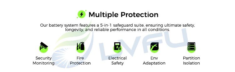
- DC input protection uses a load switch and fuse.
- The battery cabinet includes a fire controller and composite fire detector.
- Two non-stored-pressure perfluorohexanone fire-extinguishing devices are listed in the published cabinet configuration.
- A water-firefighting connection and fire hose are included in the published fire-protection design.
- An emergency-stop switch, manual switch, sound-and-light alarm, warning light and running light are included.
- A dehumidifier is included to reduce condensation risk inside the cabinet.
Operating Modes and Applications
Peak Shaving and Time-of-Use Energy Management
The EMS can schedule charging and discharging by time period. The system can charge during lower-price periods and discharge during peak-price or high-demand periods, subject to the site's tariff structure and operating strategy.
Solar Self-Consumption and Export Control
In a PV-storage configuration, the system can use surplus photovoltaic generation to charge the battery and discharge stored energy when site demand exceeds PV output. The published application description also supports curtailing PV output after the battery reaches its configured charge limit to prevent reverse power flow where zero-export operation is required.
Backup Power and Microgrids
With the configured bidirectional PCS and STS, LVFU's published application description specifies transfer to battery backup within 20 ms during a grid outage. Transfer performance depends on the selected electrical-cabinet configuration, system commissioning and site operating conditions.
Typical Project Types
Typical applications include factories, industrial parks, commercial buildings, data centers, PV-storage-charging stations, island power systems, remote commercial sites and other microgrid projects.
Capacity Expansion
LVFU's published system description states that one 400 V electrical cabinet can support up to four 261 kWh battery cabinets. This extends nominal storage duration from approximately two hours with one cabinet to up to eight hours with four cabinets, subject to project design and the selected electrical configuration.
Technical Documents
The LVFU download center lists an LF-ESS-261 user manual and a 125 kW / 261 kWh C&I BESS datasheet. Use the current documents to confirm the final project configuration, installation requirements and model-specific ratings.
LF-ESS-261 FAQ
What is the LF-ESS-261?
The LF-ESS-261 is a 125 kW / 261 kWh commercial and industrial battery energy storage system. It combines a liquid-cooled 261 kWh LFP battery cabinet with an electrical cabinet containing the PCS, EMS, MPPT, STS and circuit-protection functions.
How is the 261 kWh battery capacity configured?
The battery cabinet contains five packs rated at 52.2 kWh each. Each pack uses 52 LFP cells connected in series, with each cell rated at 3.2 V and 314 Ah.
How long can a 261 kWh battery support a 100 kW load?
The theoretical duration is 2.61 hours, calculated as 261 kWh divided by 100 kW. Actual runtime is lower after accounting for the usable state-of-charge window, PCS losses, auxiliary loads, temperature and battery protection limits.
Why is the PCS rated at 125 kW?
The 125 kW PCS gives the 261 kWh system a nominal duration of approximately 2.09 hours at rated power. It also remains within the battery cabinet's published 0.5C rating, which corresponds to approximately 130.5 kW at nominal capacity.
Can the LF-ESS-261 be expanded?
LVFU's published system description states that up to four 261 kWh battery cabinets can operate with one 400 V electrical cabinet, extending the nominal system duration from approximately two to eight hours.
What communication interfaces does the battery cabinet support?
The published battery-cabinet specification lists RS485 and Ethernet interfaces with IEC 61850, Modbus RTU and Modbus TCP protocols.
Is the entire LF-ESS-261 cabinet rated IP55?
The published specification assigns IP55 to the battery compartment and IPX4 to the liquid-cooling chamber. These ratings should not be presented as a single IP55 rating for every compartment without additional model-specific evidence.
Which certifications apply to the LF-ESS-261?
Certification requirements vary by market and final system configuration. Request the current model-specific certificate package from LVFU and verify the certificate scope, model number and destination-market requirements before procurement.
