

Commercial and industrial (C&I) energy storage systems provide distributed storage solutions for industrial and commercial users. Their core functions include energy time-shifting, demand charge management, and emergency backup power. From an architectural perspective, a C&I storage system consists of four core subsystems – the battery system, BMS, PCS, and EMS (often referred to as “3S + Battery”) – working alongside auxiliary systems such as thermal management, fire protection, power distribution, and monitoring. This article breaks down each component and its role within the overall system.
It is worth noting that C&I storage differs significantly from residential storage in several key aspects: system voltage (600–1500V vs. 48–400V), unit power rating (100kW-class vs. 5–10kW-class), grid-connection requirements, fire protection complexity, and EMS dispatch sophistication. This article focuses specifically on the C&I application scenario.
Part 1: Core Systems – The 3S + Battery
Note: The “3S” refers collectively to the three core control systems – BMS (Battery Management System), PCS (Power Conversion System), and EMS (Energy Management System).
1. Battery System – The Energy Storage Carrier
The battery system serves as the physical medium for energy storage. Currently, most systems use LiFePO₄ (lithium iron phosphate) cells – typically 280Ah or 314Ah models. The system voltage typically ranges from 600V to 1500V DC, although some smaller systems (below 100kW) may operate at 400–600V DC. The physical architecture follows a hierarchical integration path: cell → module → PACK → battery cluster. Multiple clusters connect in parallel to feed the DC side of the PCS.
2. BMS (Battery Management System) – The Monitoring and Protection Core
The BMS monitors and manages the battery system. It continuously tracks cell voltage, temperature, and current, accurately calculates State of Charge (SOC) and State of Health (SOH), and performs cell balancing. Industrial-grade BMS typically adopts a three-tier architecture: BMU (cell/module-level monitoring unit) → BCMU (cluster-level management unit) → BAMS (array-level/system-level management unit). This tiered structure provides graded protection and coordinated control from the individual cell up to the entire system.
3. PCS (Power Conversion System) – The Bidirectional Power Interface
The PCS handles bidirectional conversion between the battery’s DC power and the grid/load’s AC power. At the same time, it executes precise charge and discharge power control. In C&I applications, PCS units commonly range from 100kW to 250kW, featuring modular parallel connection, anti-reverse power flow protection, and low-voltage ride-through capability. Conversion efficiency typically exceeds 97%.
4. MPPT Optimizer – Dedicated to DC-Coupled Systems
The MPPT (Maximum Power Point Tracking) controller continuously tracks the PV array’s maximum power output point. This ensures that the PV system generates at optimal efficiency regardless of changing sunlight and temperature conditions. In a DC-coupled architecture, the MPPT output feeds directly into the battery bank, eliminating one AC/DC conversion stage and boosting overall system efficiency.
5. STS (Static Transfer Switch) – The Mode-Switching Actuator
The STS (Static Transfer Switch) serves as the execution unit for switching between grid-tied and off-grid modes. When the grid experiences disturbances, the STS transfers the power source from the grid to the storage system within milliseconds. This ensures that critical loads continue running without interruption – a vital feature for industrial and commercial users with high reliability requirements.
6. EMS (Energy Management System) – The Decision-Making Brain
The EMS functions as the system’s central decision-maker. It uses electricity price signals, load forecasts, and PV generation data to formulate optimal charge/discharge strategies – for example, peak-valley arbitrage, peak shaving, and PV self-consumption optimization. In addition, it aggregates data from the BMS, PCS, and power meters to provide comprehensive system monitoring and coordinated safety control. For systems that interact with the grid, the EMS can also respond to utility dispatch commands, participating in demand response programs or virtual power plant (VPP) aggregation to unlock additional revenue streams.
Part 2: Auxiliary and Support Systems
1. Thermal Management System
The thermal management system maintains battery temperature within the optimal operating range of 20–30°C. Two main approaches exist: air cooling and liquid cooling. Liquid cooling has become the preferred choice for high-capacity systems, as it offers superior heat dissipation efficiency and better temperature uniformity.
2. Fire Protection System
The fire protection system deploys smoke detectors, temperature sensors, and combustible gas detectors, combined with gas-based fire suppression agents such as HFC-227ea (heptafluoropropane) or FK-5-1-12 (perfluorohexanone). The system integrates with the BMS and EMS to form a three-tier protection sequence: early warning → system shutdown and isolation → fire suppression agent release. This layered approach effectively contains thermal runaway propagation.
3. Power Distribution and Electrical System
This subsystem includes DC combiner cabinets, AC distribution cabinets, isolation transformers (optional), and surge protection/grounding devices. Together, they handle energy collection, distribution, and protective functions.
4. Monitoring and Communication System
The monitoring and communication system provides local touchscreen interfaces and remote operation platforms. These tools enable real-time status viewing, fault diagnostics, and OTA (over-the-air) upgrades – meeting the requirements for unattended operation.
Part 3: Integrated Form Factors
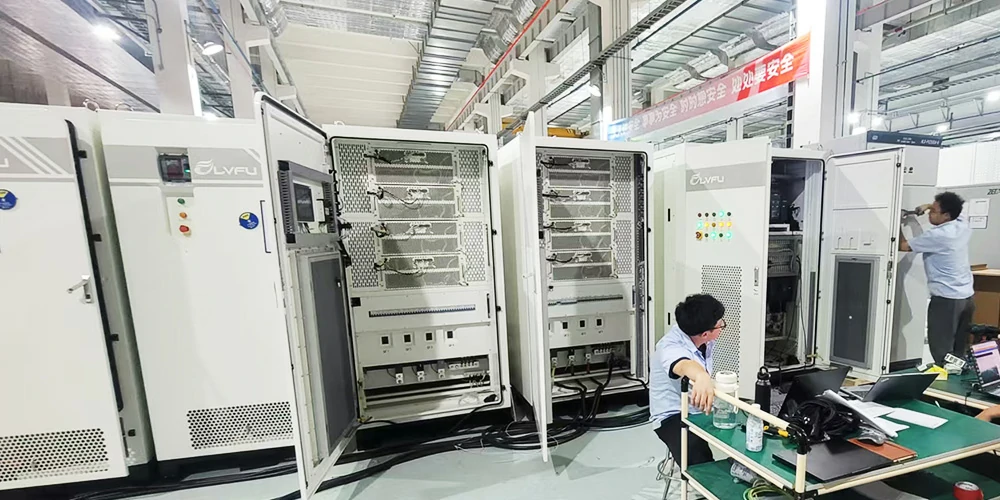
Currently, the mainstream product for C&I storage is the outdoor integrated cabinet. This configuration integrates the battery clusters, PCS, BMS, EMS, thermal management, fire protection, and power distribution all within a standardized enclosure – common specifications include 100kW/200kWh and 125kW/258kWh. This integrated approach delivers several key benefits: small footprint, simplified installation, and consistent quality control.
From a system architecture perspective, two coupling options exist:
- AC coupling – suited for retrofitting existing PV systems
- DC coupling – suited for new installations, offering higher integration efficiency
Part 4: System Operating Logic – How the Subsystems Work Together
A complete C&I storage system follows a closed-loop operating sequence:
“Sense → Decide → Execute → Feedback”
1. Sense: The BMS continuously monitors battery status (voltage, temperature, SOC, SOH) and sends data to the EMS. At the same time, power meters collect real-time load and grid interaction data.
2. Decide: The EMS processes this information alongside electricity price signals, load forecasts, and PV generation data to calculate the optimal charge/discharge strategy.
3. Execute: The EMS issues power commands to the PCS, which then controls the charge/discharge direction and power level accordingly.
4. Feedback: The BMS continues to monitor the battery and feeds updated data back to the EMS, enabling closed-loop adjustments.
Meanwhile, the STS continuously watches grid status. Once it detects a grid anomaly, it transfers the system from grid-tied to off-grid mode within milliseconds, ensuring that critical loads remain powered without interruption.
Part 5: Typical Application Scenarios
C&I energy storage systems serve three primary application scenarios:
1. Peak-Valley Arbitrage – The system charges during low-tariff periods and discharges during high-tariff periods, reducing overall electricity costs. This currently represents the primary revenue model for C&I storage.
2. Demand Charge Management – By discharging during peak demand periods, the system reduces the facility’s peak power draw from the grid. This lowers the capacity/demand charge component of the electricity bill.
3. Emergency Backup Power – When a grid outage occurs, the system automatically switches to off-grid mode. This keeps production equipment, data centers, and other critical loads running – preventing costly production interruptions.
The safety and economic performance of a C&I energy storage system ultimately depend on proper component selection and seamless coordination across all subsystems. Understanding this architectural logic provides the foundation for effective system design and equipment specification. As technology matures and costs continue to decline, C&I storage will unlock even greater economic and strategic value across a widening range of applications.
