

Energy storage battery performance and lifespan depend heavily on installation quality. Unfortunately, common installation mistakes often go unnoticed, yet their impact runs deep. At best, they accelerate capacity fade; at worst, they trigger thermal runaway and other safety hazards. Therefore, proper installation practices are critical.
In practice, installers should focus on three typical problem areas: insufficient spacing between batteries, poor ventilation and heat dissipation design, and improper tightening torque on wiring terminals. These seemingly minor deviations accumulate over long-term operation, ultimately weakening the system’s overall reliability and economic performance. As a result, installation teams must strictly follow the manufacturer’s technical manual and industry standards, implementing each construction requirement one by one to eliminate hidden risks at the source. Only by maintaining a meticulous installation approach throughout can we ensure the energy storage system operates safely, efficiently, and stably across its entire lifecycle.
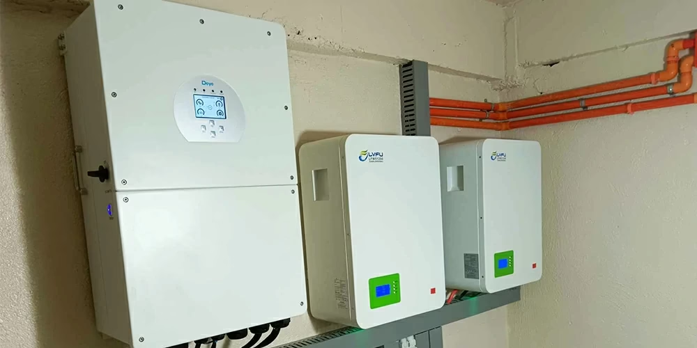
Part 1: Common Installation Mistakes
1. Reversed positive and negative wiring (the most serious mistake). This directly causes an internal battery short circuit or burns out the protection board, leading to irreversible damage or even a fire.
2. Connecting low-voltage batteries in series instead of parallel. This error causes system voltage to rise abnormally, easily piercing the insulation of inverters or load equipment and causing permanent equipment damage.
3. MC4 connectors not fully locked or mismatched in model. This increases contact resistance and causes localized overheating. Over time, it can melt the insulation layer and trigger DC-side arc faults.
4. Communication cables and power cables routed together or with insufficient spacing. This easily generates electromagnetic interference, causing communication packet loss and data anomalies. Consequently, it affects monitoring accuracy and dispatch command execution. In severe cases, it may trigger false alarms or prevent the BMS from accurately assessing state of charge.
5. Insufficient spacing between cabinets. This blocks air convection and causes heat accumulation. Long-term high-temperature operation accelerates cell aging and capacity fade, significantly increasing thermal runaway risk. Therefore, always reserve adequate heat dissipation channels.
6. Ambient temperature and humidity exceeding allowable ranges. Exceeding specified thresholds accelerates cell aging and induces corrosion. Ensure the installation environment meets manufacturer requirements, and configure temperature control equipment when necessary to maintain suitable operating conditions.
Part 2: Prevention and Corrective Measures
1. Strictly verify battery pack positive and negative markings. Use a multimeter to confirm correct polarity before wiring. We recommend conducting a dedicated briefing for installation personnel before connection and implementing a two-person verification system to ensure correct wiring.
2. Carefully identify wiring topology for low-voltage parallel scenarios. Never mistakenly connect battery packs that should be in parallel as a series connection. This prevents abnormal voltage rise from piercing inverter or load equipment insulation. Before construction, draw a clear wiring topology diagram and set physical error-prevention markers at key nodes to eliminate wiring logic errors at the source. After completing the connection, measure the total voltage again to ensure it meets system design expectations, preventing equipment damage from topology confusion.
3. Standardize MC4 connector installation. Select original matching models and ensure connectors fully engage with an audible locking sound. After installation, use a dedicated tension meter to spot-check connection tightness. Regularly use infrared thermometry to identify abnormal hot spots, ensuring contact resistance remains within safe limits.
4. Implement classified and layered cable routing. Maintain specified spacing between power cables and signal cables, or apply shielding measures. This effectively suppresses electromagnetic interference and ensures stable communication links and accurate data monitoring.
5. Strengthen heat dissipation space management. Strictly follow the cabinet spacing standards specified in the manufacturer’s manual. Ensure air convection channels remain unobstructed to avoid heat accumulation and thermal runaway risk.
6. Establish an environmental monitoring and warning mechanism. Monitor temperature and humidity data in real time. Once values exceed limits, immediately trigger audible and visual alarms and activate air conditioning or dehumidification. This prevents condensation corrosion or high-temperature accelerated aging, keeping the storage environment within safe thresholds at all times.
