Classification of PACK Battery Packs
Three Electric Systems of New Energy Vehicles
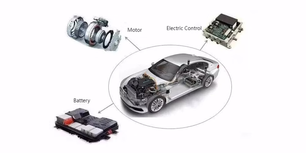
Three Electric Systems of New Energy Vehicles
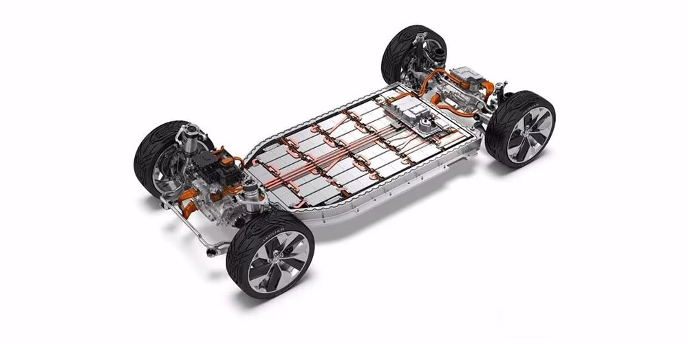
Battery Pack (PACK) and Chassis Integration
What is a PACK Battery Pack?
To understand what a PACK battery pack is, it helps to break down the basic hierarchy of lithium batteries: cells, modules, and packs.
- Battery Cell (cell): Think of a battery cell as the fundamental building block. It’s a single unit that typically provides between 3V and 4V. You can’t get more basic than this.
- Battery Module (Batteries): Now, when you group several of these cells together, you create a battery module. This bundle connects the cells within a single frame or housing, boosting both the overall voltage and capacity compared to a lone cell.
- Battery Pack (pack): Finally, a complete battery pack (PACK) is what you actually get from a manufacturer. It essentially integrates multiple modules and combines them with other critical components—most importantly, a Battery Management System (BMS) to monitor and protect the battery. So, the pack is the ready-to-use final product delivered to the customer.
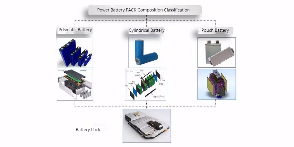
Composition Classification of PACK
As the core component of the PACK, battery cells are primarily grouped into three shape‑based categories: prismatic, cylindrical, and pouch (also called polymer). Manufacturers produce these by packaging the positive and negative electrode plates into their corresponding casings—each type uses a slightly different packaging process.
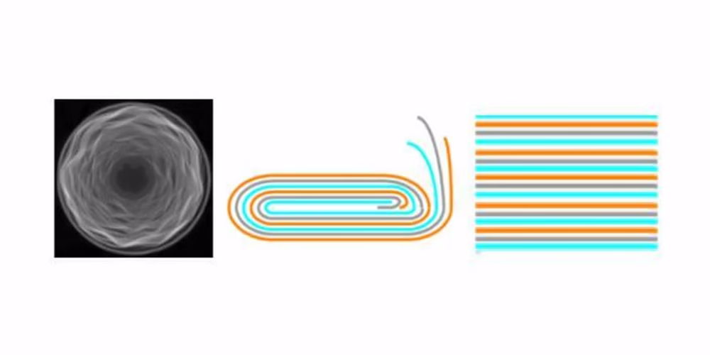
- Left-Cylindrical Winding
- Middle-Prismatic Winding
- Right-Prismatic Stacking
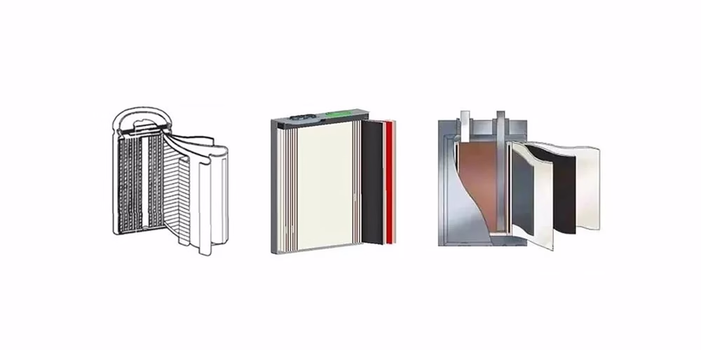
- Left-Cylindrical Cell
- Middle-Prismatic Cell
- Right-Pouch Cell
Battery Module
In the assembly stage, battery cells are connected in different series and parallel configurations using busbars and various joining methods. Options include screw fastening, resistance welding, ultrasonic welding, ultrasonic aluminum wire bonding, and laser welding.
When weighing factors such as production yield, efficiency, and the internal resistance of connection points, many battery manufacturers now choose laser welding as their preferred process.
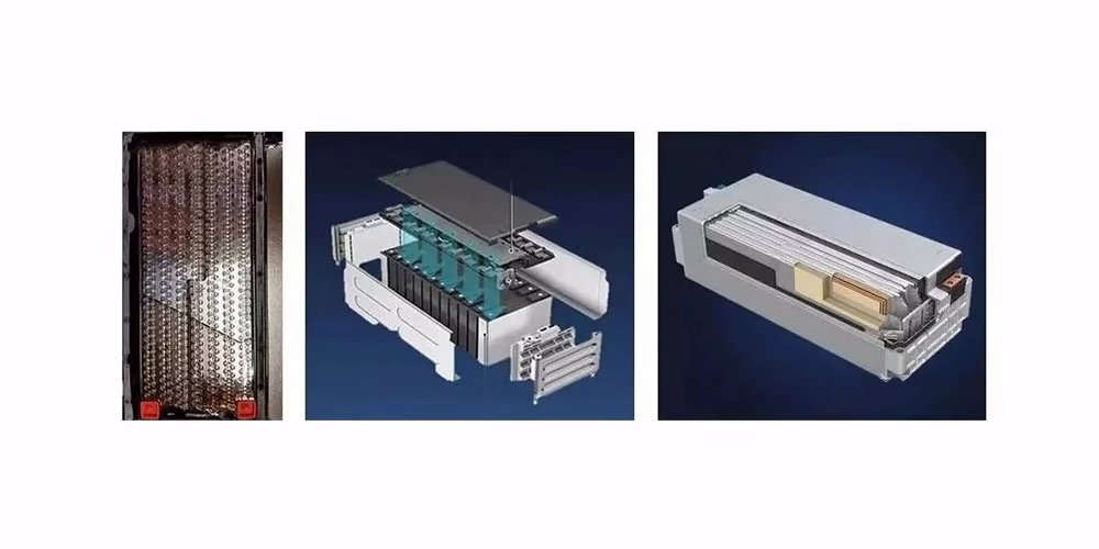
- Left-Cylindrical Module
- Middle-Prismatic Module
- Right-Pouch Module
PACK Battery Pack
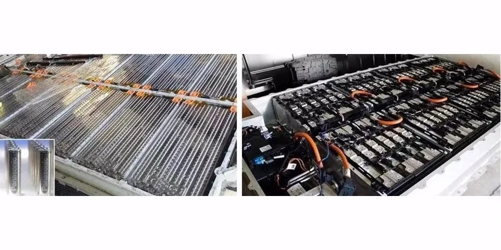
- Left-Cylindrical PACK
- Right-Prismatic PACK
- Pouch PACK
Composition of PACK Battery Packs
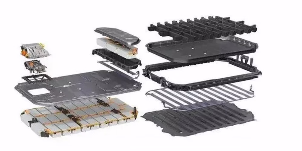
A complete battery PACK integrates several key subsystems. These mainly include the battery module itself, the mechanical system, the electrical system, the thermal management system, and the Battery Management System (BMS).
Battery Module
Think of the battery module as the “heart” of the entire pack. Its core function is to store and release the electrical energy that powers the vehicle.
Mechanical System
This system forms the “skeleton” of the PACK. It comprises the upper cover, the tray, various metal brackets, end plates, and bolts. These components provide crucial structural support, protect against mechanical shock and vibration, and ensure environmental sealing (waterproof and dustproof).
Electrical System
Here, we find the “circulatory and nervous systems.”
- The high-voltage harness acts as the “main artery,” carrying high-power energy from the battery to the vehicle’s components.
- The low-voltage harness functions as the “neural network,” transmitting real-time detection and control signals throughout the pack.
Thermal Management System
You can think of this as the pack’s built-in “air conditioning.” Common types include air cooling, water cooling, liquid cooling, and phase-change material systems. In a water-cooling setup, for example, you’ll find components like cooling plates, water pipes, and thermal interface materials (e.g., insulation and thermal pads) working together to regulate temperature.
Battery Management System (BMS)
The BMS serves as the “brain.” It consists of two main units working in tandem:
- The Cell Monitor Unit (CMU) measures the voltage, current, and temperature of individual cells or groups. It also performs cell balancing. Once collected, the CMU sends this vital data to the BMU via the low-voltage harness (“neural network”).
- The Battery Management Unit (BMU) analyzes the data from the CMU. If it detects any abnormal conditions, it protects the battery by requesting reduced current or by cutting off the charge/discharge path entirely. Beyond protection, the BMU also manages the battery’s state of charge and temperature. Following pre-programmed control strategies, it determines when to issue warnings and relays them to the vehicle controller—and ultimately, to the driver.
- BMU: Battery Management Unit. Responsible for evaluating the data transmitted by the CMU. If the data is abnormal, it protects the battery by issuing a request to reduce the current or cutting off the charge/discharge path to prevent the battery from exceeding the permitted operating conditions. It also manages the battery’s state of charge and temperature. Based on the pre-designed control strategy, it determines the parameters and states that require warning and sends the warning to the vehicle controller, which is finally transmitted to the driver.
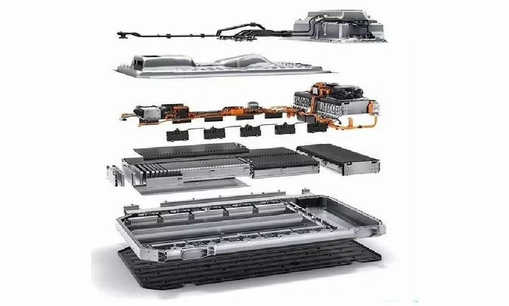
PACK Battery Pack Exploded View
PACK Component Comparison Table
| No. | Cylindrical | Prismatic | Pouch |
| 1 | PACK Base | Upper Casing | Upper Casing |
| 2 | PACK Upper Cover | Lower Casing | Lower Casing |
| 3 | PACK Upper Cover | Battery Module | Battery Module |
| 4 | Water Cooling System | Water Cooling System | Water Cooling System |
| 5 | Sealing Component | Sealing Component | Sealing Component |
| 6 | Low Voltage Harness | Low Voltage Harness | High Voltage Harness |
| 7 | High Voltage Harness | BMS Power Controller | BMS Power Controller |
| 8 | BMS Power Controller | Fixed Bracket | Fixed Bracket |
| 9 | Module Fixing Screw | Thermal Pad | Thermal Pad |
| 10 | BDU | BDU | BDU |
| 11 | Series Connection Tab | Positive Terminal Outlet | Positive Terminal Outlet |
| 12 | Positive Terminal Outlet | Communication Port | Communication Port |
| 13 | Communication Port | Insulation Spacer | Insulation Spacer |
| 14 | Insulation Spacer | Connector | Connector |
| 15 | Connector | Explosion-proof Valve) | Explosion-proof Valve |
| 16 | Explosion-proof Valve | High Voltage Busbar | High Voltage Busbar |
| 17 | High Voltage Busbar | High Voltage Box | High Voltage Box |
| 18 | High Voltage Box | Current Sensor | |
| 19 | Current Sensor | Pre-charge Resistor | |
| 20 | Pre-charge Resistor | Connector | |
| 21 | Connector | Clip | |
| 22 | Clip |
Manufacturing Process
The battery PACK is the core energy source for new energy vehicles, providing driving power for the entire vehicle. As a core component of new energy vehicles, its quality directly determines the performance of the entire vehicle. Lithium battery manufacturing equipment is generally divided into three stages: front-end equipment, mid-end equipment, and back-end equipment. The precision and automation level of the equipment will directly affect the production efficiency and consistency of the product.
Although the types of cells and modules are different, the composition and manufacturing process of the PACK are generally the same (not all manufacturers have the same process flow). The figure below is for reference.
PACK Assembly Process Flow
It is mainly divided into assembly process, air tightness detection process, software writing process, and electrical performance detection process.
Image 9 Description (Page 9) – PACK Assembly Process Flow Diagram:
| Stage | Process Step (English) |
| Main Line | Automatic loading of lower casing |
| Lower casing gluing | |
| Install connector | |
| Install thermal pad/insulation sheet | |
| Install water cooling plate/coolant | |
| Prismatic cell air tightness test | |
| Module fixing | |
| EOL Test | |
| Upper casing assembly | |
| Air tightness test | |
| Outbound | |
| Branch Line | BDU installation |
| Module installation | |
| Battery installation | |
| Module fixing | |
| Collection harness | |
| Collection harness connected to BMS | |
| Harness organization | |
| Label application | |
| Charging test | |
| Note | Main line process |
| Branch line process | |
| In-stock process | |
| PACK Assembly Process Flow |
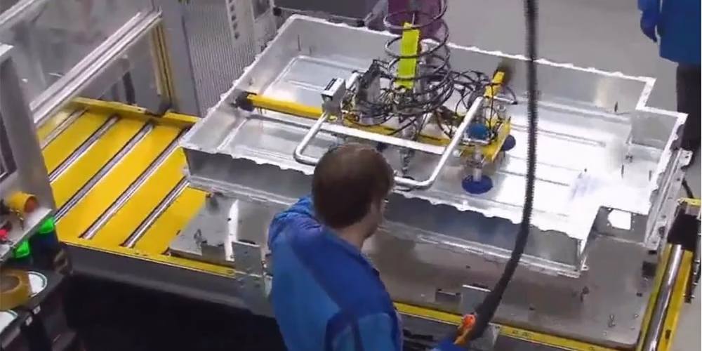
Production Line Introduction
In the PACK assembly process, there are many flexible circuits and press-fitting/tightening operations. The difficulty of automation and the low return on investment make the automation level of the back-end equipment relatively lower than that of the front-end and mid-end. However, it can be compatible with the assembly of three types of PACK battery packs: cylindrical, prismatic, and pouch.
Positions that may require automation:
- Automatic loading of the lower casing
- Automatic loading of the module into the casing
- Module fixing and tightening
- Upper cover loading and tightening
- Automatic application of A/B thermal adhesive (depending on the process)
- Automatic application of sealant (depending on the process)
- Finished product off-line
In addition, some may require automatic installation and tightening of copper plates and screws, air tightness testing, and EOL testing. These are less common, and stability is more difficult to guarantee.
There are two main types of operation for mass production equipment on the back-end PACK line:
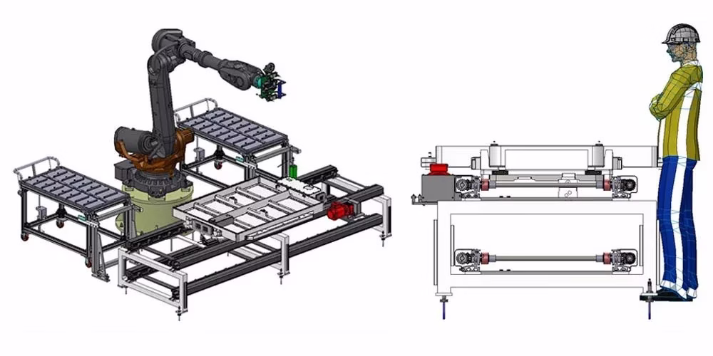
1. AGV + Assembly Trolley
This was previously mainly used in car factories, and battery factories are gradually promoting this model.
AGV Conveying Line Process
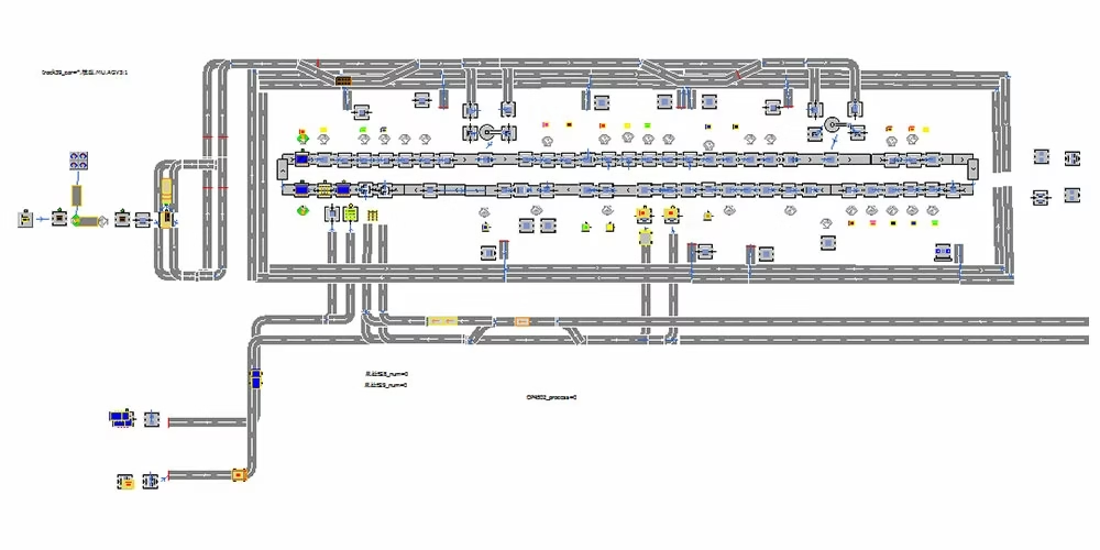
AGV Line Logistics Simulation
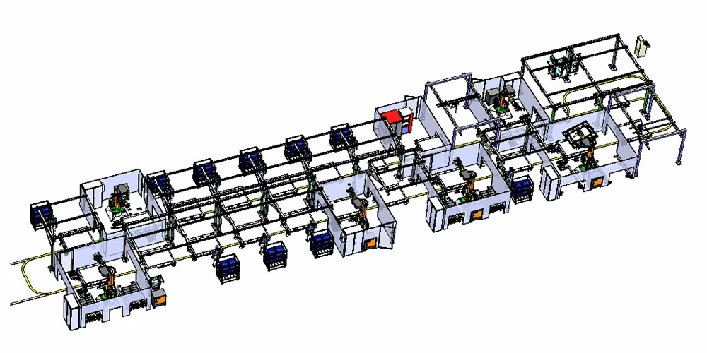
2. Conveying Line + Pallet Mode
Roller conveyor / friction roller conveyor / multi-strand chain conveyor
Conveying Line Process
Summary
The above is a basic introduction to lithium battery PACK knowledge.
With the gradual maturity of the power battery industry, battery PACK modularization technology will inevitably become more and more mature. The development of battery PACK technology involves knowledge from multiple disciplines and fields, requiring cross-disciplinary technological integration.
In conclusion, for car companies to ultimately achieve large-scale production of PACK products that fully meet the requirements for lifespan, stability, reliability, and safety at the new energy vehicle level, a large amount of engineering practice and testing verification, as well as continuous product optimization and upgrading, are still required.